 English
What Are the Common Causes of Thermal Overload Protector Tripping?

Introduction: Understanding Thermal Overload Protectors
Thermal overload protectors (TOPs) are critical safety devices used to guard electric motors and other equipment from overheating. They detect abnormal temperature rises—usually caused by excessive current or stalled conditions—and interrupt the circuit before insulation, windings, or connected systems are damaged. Despite their straightforward purpose, repeated or unexpected tripping can be frustrating and costly. This article explains the most common causes of TOP tripping, how to diagnose each cause practically, and proven corrective measures that technicians and maintenance teams can apply.
How Thermal Overload Protectors Work
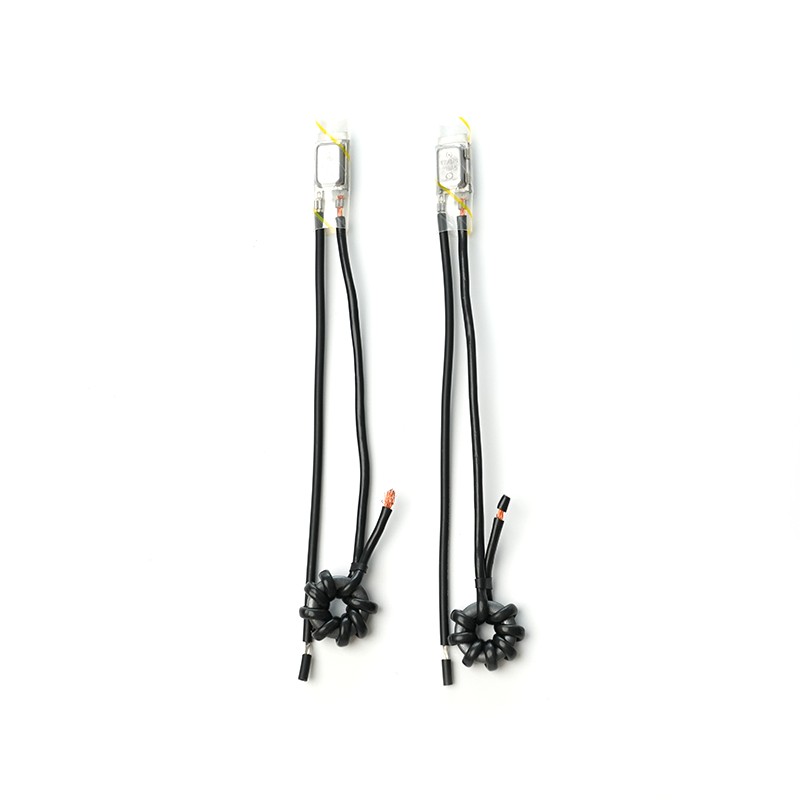
A thermal overload protector generally relies on a bimetallic strip, a thermistor, or a thermal fuse to sense temperature or current-induced heat. In motors, TOPs are often embedded in the winding or mounted on the motor frame to closely track the motor’s thermal state. When the sensed temperature exceeds the preset threshold for a defined time, the protector opens the circuit, stopping current flow. Many TOPs are automatic reset types, while others require manual reset to ensure inspection before restart.
Electrical Causes of TOP Tripping
Overcurrent and Overload Conditions
One of the primary electrical causes is sustained overcurrent, which often results from mechanical overload (too high a load on the motor shaft), jammed equipment, or process upsets. When current draw remains above nominal for extended periods, heat builds up in windings and triggers the TOP. Evaluate load profiles and measure running current to confirm overload conditions.
Short Circuits and Phase Loss
Intermittent short circuits or a single-phase loss in a three-phase motor causes unbalanced currents and localized overheating. Phase loss (open phase) often forces remaining phases to carry extra current, producing higher temperatures that the TOP senses. Use clamp meters and insulation testers to verify continuity and phase integrity.
Incorrect Protector Sizing or Setting
Selecting an incorrectly rated TOP—one with a trip curve or temperature setting not matching the motor’s nameplate specifications—will increase nuisance tripping. TOPs must match motor full-load current (FLC), expected inrush characteristics, and ambient conditions. Review spec sheets and ensure the protector’s trip class and calibration match the motor application.
Mechanical and Thermal Causes
Poor Ventilation and Cooling System Failures
Motors and enclosures depend on airflow to remove dissipated heat. Blocked ventilation fans, clogged filters, or obstructed vents raise internal temperature. External cooling systems (coolant pumps, heat exchangers) that fail or underperform will have the same effect. Regularly inspect and clean cooling paths, verify fan operation, and measure ambient temperature.
Bearing or Mechanical Friction
Worn bearings, misalignment, or inadequate lubrication produce extra mechanical friction and increase load torque. The motor draws more current to overcome this resistance, generating heat that triggers TOPs. Mechanical inspection, vibration analysis, and periodic lubrication eliminate many such causes.
Seized or Jammed Driven Equipment
If the driven load (gearbox, pump, conveyor) is jammed or heavily impeded, the motor can stall or operate at high load causing rapid temperature rise. Inspect coupling, driven devices, and system interlocks. Implement torque-limiting devices or sensors to detect abnormal torque before it leads to thermal trips.
Environmental and Installation Factors
High Ambient Temperatures
TOPs are calibrated for standard ambient ranges. Operating a motor in high ambient temperature environments (e.g., enclosed cabinets with poor ventilation or hot industrial processes) reduces the thermal margin and can cause tripping at normal loads. Use higher-rated TOPs, improve enclosure ventilation, or provide external cooling to compensate.
Incorrect Mounting or Poor Thermal Contact
TOPs embedded in or mounted on motor surfaces must have good thermal contact. Loose clips, improper positioning, or insulating coatings between the protector and the motor frame delay heat transfer or produce inaccurate readings. Re-seat protectors correctly and follow manufacturer mounting guidelines.
Vibration and Mechanical Stress
High vibration environments can loosen electrical connections, damage sensors, or cause intermittent contacts within the protector assembly. Perform vibration diagnostics and secure wiring and protectors against mechanical fatigue. Replace protectors showing signs of physical damage.
Component Degradation and Manufacturing Issues
Aging, Drift, and Component Failure
Thermal protectors and their sensing elements degrade over time; calibration drifts, bimetal fatigue, or thermistor drift can cause premature or delayed tripping. Implement a lifecycle replacement schedule, perform bench calibration checks, and keep spares to reduce downtime.
Factory Defects and Inconsistent Quality
Occasionally, protectors suffer from manufacturing defects such as improper stamping, poor solder joints, or inconsistent thermal settings. When multiple units from the same batch trip unexpectedly, work with the supplier to test samples and review manufacturing traceability and quality control records.
Diagnostics: Practical Steps to Identify the Root Cause
A structured approach reduces guesswork and repair time. Follow these diagnostics steps in sequence:
- Record operating currents (start, no-load, and full-load) using a clamp meter to identify overcurrent conditions.
- Check supply voltage and phase balance; measure for phase loss or undervoltage.
- Inspect mechanical load, bearings, coupling, and driven machine for signs of friction, jamming, or increased torque demand.
- Verify ventilation, clean cooling passages, and confirm fan or coolant system operation.
- Test the TOP directly: measure resistance/continuity at room temperature and heat the sensor (following safety procedures) to see trip behavior.
- Review recent process changes or maintenance events that coincide with tripping incidents.
Corrective Actions and Best Practices
Match Protector Specification to Application
Select TOPs based on motor FLC, inrush current, ambient conditions, and required trip class. Where variable loads or frequent starts occur, choose protectors with appropriate delay characteristics to tolerate inrush without sacrificing protection.
Improve Cooling and Ventilation
Design enclosures for airflow, add external fans or heat exchangers where necessary, and institute routine cleaning schedules for filters and vents to maintain thermal margins.
Mechanical Maintenance and Condition Monitoring
Regular lubrication, alignment checks, and vibration monitoring prevent excessive friction and abnormal loads. Use condition-based maintenance (CBM) to predict failures before they trigger thermal trips.
Electrical Health and Protective Coordination
Ensure upstream protective devices—fuses, circuit breakers, and overload relays—are coordinated with the TOP. Correct coordination prevents nuisance trips while maintaining safety. Address loose connections and verify terminal tightness periodically.
Quick Reference Table: Causes vs. Solutions
| Cause | Symptoms | Immediate Fix | Long-Term Action |
| Mechanical overload | High running current, slow or hot motor | Reduce load, inspect coupling | Redesign process, add torque limiter |
| Poor ventilation | Gradual temperature rise, ambient hot | Improve airflow, clean vents | Install fans/heat exchangers |
| Phase loss | Vibration, humming, uneven torque | Stop immediately, check supply | Install phase monitoring relay |
Conclusion: A Practical Mindset to Reduce TOP Tripping
Thermal overload protector tripping is a warning sign, not an inconvenience to ignore. Systematic diagnosis—starting with electrical measurements, then mechanical inspection, and finally component testing—will quickly reveal root causes. Matching protector specifications, keeping cooling systems healthy, and instituting solid mechanical and electrical maintenance regimes minimize downtime and extend equipment life. By combining practical troubleshooting with preventive measures, maintenance teams can convert each trip into an opportunity to improve system reliability and safety.


As China Thermal Protectors Manufacturers,Provide customers with high-quality and reliable protectors and electrical product safety protection solutions.
-
Tel:+86-515-88498139
-
Email:[email protected]
-
Phone:+86-13913681876
-
Add: Building C, No. 888 Huanhu West Second Road, Lingang New Area, China (Shanghai) Pilot Free Trade Zone
